Is there a tutorial or FAQ for the IO expansion module that someone can link for me? I know what to do to read a port (I) on the IO but I want to know what I need to do to send to a port (O). The manual and sample code only cover reading the ports. Searching for "IO Module" yields *far* too many unrelated results to sift through.
Thanks,
Charlie
IO Module tutorial or FAQ?
Re: IO Module tutorial or FAQ?
LOL...
You caught me on that
We never implemented the Output functions.
JSClownfish has done so on his module, but he did it himself.
You will need to upload a new firmware into the I/O module:
Then, you can use this to set channels in your INO code:
Place it at the very end of your code after the last }
To set ports, you can call the function like this:
Let me know if that works.
You caught me on that
We never implemented the Output functions.
JSClownfish has done so on his module, but he did it himself.
You will need to upload a new firmware into the I/O module:
Code: Select all
#include <Wire.h>
#include <avr/wdt.h>

byte IOports[] ={
  3,5,6,9,10,11};
byte ChannelValue[] = {
  0,0,0,0,0,0};
byte cmdnum=255;
byte datanum=255;

byte IOOut=0;
void setup()
{
  wdt_enable(WDTO_1S);
  Wire.onReceive(receiveEvent);
  Wire.onRequest(requestEvent);
  Wire.begin(9);
  for (int a=0;a<6;a++)
  {
    pinMode(IOports[a],INPUT);
    digitalWrite(IOports[a],HIGH); //pull up resistor
  }
}

void loop()
{
  wdt_reset();
  if (cmdnum!=255)
  {
    ProcessCMD(cmdnum,datanum);
    cmdnum=255;
    datanum=255;
  }
}

void requestEvent() {
  IOOut=0;
  for (int a=0;a<6;a++)
  {
    IOOut+=digitalRead(IOports[a])<<a; //pull up resistor
  }
  Wire.write(IOOut);
}

void receiveEvent(int howMany) {
  wdt_reset();
  if (howMany==5)
  {
    byte cmd1, cmd2, cmd3, cmd4, cmd5;
    cmd1=Wire.read();
    cmd2=Wire.read();
    cmd3=Wire.read();
    cmd4=Wire.read();
    cmd5=Wire.read();
    if (cmd1=='$' && cmd2=='$' && cmd3=='$')
    {
      cmdnum=cmd4;
      datanum=cmd5;
      //Serial.println(cmd4,DEC);
      //Serial.println(cmd5,DEC);
    }
  }
  else
  {
    for (int a=0;a<howMany;a++)
    {
      Wire.read();
    }
  }
}

void ProcessCMD(byte cmd, byte data)
{
  wdt_reset();
  // Individual Channel
  if (cmd>=0 && cmd<=5)
  {
    ChannelValue[cmd]=data;
    pinMode(IOports[cmd],OUTPUT);
    analogWrite(IOports[cmd],data);
  }
}
Code: Select all
void IOSetChannel( byte channel, boolean status)
{
  Wire.beginTransmission(I2CIO);
  Wire.write("$");
  Wire.write("$");
  Wire.write("$");
  Wire.write(channel);
  Wire.write(status?255:0);
  Wire.endTransmission();
}
To set ports, you can call the function like this:
Code: Select all
IOSetChannel(0,HIGH); // Sets channel 0 to HIGH
IOSetChannel(1,LOW); // Sets channel 1 to LOW
Roberto.
Re: IO Module tutorial or FAQ?
Thanks, Roberto. I'll test it out this week and see if I can't get it working.

Just change the name to "I Module Expansion" you should be goodYou caught me on that
Re: IO Module tutorial or FAQ?
Roberto,
I want to test the IO separate from the RA right now. I assume that I can treat it as a typical Arduino board, yes? I want to upload a variant of the Blink code (http://www.arduino.cc/en/Tutorial/BlinkingLED) so I can test my 5v relay while I still have it on the breadboard. From the code you posted above I can use pins 3,5,6,9,10,11 correct?
~Charlie
Re: IO Module tutorial or FAQ?
Thanks again, Roberto! I finally had a chance to get back to this and was able to get it working. I still have all the hardware (relay and voltage regulator for the Eheim auto feeder) on a breadboard but it's plugged into the IO module and RA and it's doing what it should do.
~Charlie
~Charlie
-
JoelIreland
- Posts: 58
- Joined: Sat Jan 26, 2013 1:27 am
Re: IO Module tutorial or FAQ?
Hey guys, i want to do this myself. Has there been any update on this? How do I upgrade the firmware on the IO box as have not done this before, and what file do I update?
Thanks.
Thanks.
Re: IO Module tutorial or FAQ?
If you open the I/O expansion module. You will see the header that you would use for code upload. It's just like uploading codes for your RA, except you need to make sure the black wire is on the GND pin and that you select Reef Angel w/ optiboot as board.
Roberto.
-
JoelIreland
- Posts: 58
- Joined: Sat Jan 26, 2013 1:27 am
Re: IO Module tutorial or FAQ?
Ok so where is the original firmware that i am modifying?
Re: IO Module tutorial or FAQ?
The modified version is posted a few posts back. That's the one you need to upload.
The original is here:
The original is here:
Code: Select all
#include <Wire.h>
#include <avr/wdt.h>

byte IOports[] ={
  3,5,6,9,10,11};

byte IOOut=0;
void setup()
{
  wdt_enable(WDTO_1S);
  Wire.onReceive(NULL);
  Wire.onRequest(requestEvent);
  Wire.begin(9);
  for (int a=0;a<6;a++)
  {
    pinMode(IOports[a],INPUT);
    digitalWrite(IOports[a],HIGH); //pull up resistor
  }
}

void loop()
{
  wdt_reset();
}

void requestEvent() {
  IOOut=0;
  for (int a=0;a<6;a++)
  {
    IOOut+=digitalRead(IOports[a])<<a; //pull up resistor
  }
  Wire.write(IOOut);
}
Roberto.
Re: IO Module tutorial or FAQ?
Roberto,
I've had some issues with my buttons on the IO module and while troubleshooting I realized that I need some sort of "debounce" for the button presses. I'm pretty sure I have that all sorted out but that led me to a couple of schematics that make me think I'm going about the buttons all wrong and wanted to run this by you.
From my Arduino/Electrical newb-ness, I pictured the buttons I am using with the I/O module as simply completing the circuit between the port it's plugged into (0-6) and the ground on the module. I am not using any resistors this way.
Here is what is making me second guess that:

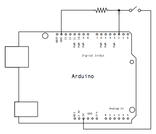
Looking at the schematics above, it looks like I should be plugging the +5v from the Arduino board into one side of the button and go to ground via a resistor on the other side. I would tie in the I/O pin on the resistor side of the button to check if I'm HIGH or LOW.
Sorry for the nomenclature but I'm still an electronics newb and don't know how to properly phrase that. I hope you can get the gist of what I'm saying.
Am I OK doing it my way I have been doing it? It has been working fine other than that odd button behavior that the debounce should fix.
[EDIT]
Or are you already taking care of that under the hood on the module?
[/EDIT]
~Charlie
I've had some issues with my buttons on the IO module and while troubleshooting I realized that I need some sort of "debounce" for the button presses. I'm pretty sure I have that all sorted out but that led me to a couple of schematics that make me think I'm going about the buttons all wrong and wanted to run this by you.
From my Arduino/Electrical newb-ness, I pictured the buttons I am using with the I/O module as simply completing the circuit between the port it's plugged into (0-6) and the ground on the module. I am not using any resistors this way.
Here is what is making me second guess that:
Looking at the schematics above, it looks like I should be plugging the +5v from the Arduino board into one side of the button and go to ground via a resistor on the other side. I would tie in the I/O pin on the resistor side of the button to check if I'm HIGH or LOW.
Sorry for the nomenclature but I'm still an electronics newb and don't know how to properly phrase that. I hope you can get the gist of what I'm saying.
Am I OK doing it my way I have been doing it? It has been working fine other than that odd button behavior that the debounce should fix.
[EDIT]
Or are you already taking care of that under the hood on the module?
[/EDIT]
~Charlie
Last edited by Piper on Thu Jul 04, 2013 6:23 pm, edited 1 time in total.
Re: IO Module tutorial or FAQ?
Well, I really is up to you to decide whether you want to use pull-up or pull-down and whether to use external resistors or the internal resistors.
Check here:
http://makezine.com/2009/03/05/understa ... ulldown-r/
I just picked pull-up and internal resistor for simplicity.
In the setup() section of the code, you will see this:
That's where I chose to use internal resistors and pulled them up, which will force the pins high on default state.
Because we are not using the pins on any load, the internal pull-up resistors should work just fine.
They are 100K if I'm not mistaken.
So, we are doing the opposite of what the design above is doing, which is pull-down with external resistor.
I think this is where you got the diagram above, but check this for debounce:
http://arduino.cc/en/Tutorial/Debounce
Check here:
http://makezine.com/2009/03/05/understa ... ulldown-r/
I just picked pull-up and internal resistor for simplicity.
In the setup() section of the code, you will see this:
Code: Select all
  for (int a=0;a<6;a++)
  {
    pinMode(IOports[a],INPUT);
    digitalWrite(IOports[a],HIGH); //pull up resistor
  }
Because we are not using the pins on any load, the internal pull-up resistors should work just fine.
They are 100K if I'm not mistaken.
So, we are doing the opposite of what the design above is doing, which is pull-down with external resistor.
I think this is where you got the diagram above, but check this for debounce:
http://arduino.cc/en/Tutorial/Debounce
Roberto.
Re: IO Module tutorial or FAQ?
Thanks, Roberto. Basically you have it all taken care of under the hood. I just need to do the debounce and keep it physically set up the way I have it.
~Charlie
~Charlie
Re: IO Module tutorial or FAQ?
Hi Roberto
I am planning to integrate the Reef Angel to my home automation system such that an alarm in the RA can play some message in the house AV system. I need to config the IO Expansion module to send out voltage to a relay. I read this post and wondering how to update the IO expansion module firmware. I opened up the IO module and there is no connector to plug in the USB-TTL. Can you guide me on this matter ?
Veeresh