Page 1 of 2
Need custom code for custom expansion
Posted: Sat Oct 20, 2012 11:22 am
by AquaO
Hi everyone,
I would like to use a arduino uno for control 4 relay to operate my dosing pumps with pin 2,4,7,8
I want that the RA talk to the arduino uno in single way, maste/slave.
Unfortunately I'm not very good in programing, but I am very confident with electronic circuits.
So I would like to have a code for the arduino uno (slave) and a code for the RA (master)
I know I could do the same thing more easily with a PWM or I/O module, but the arduino uno was given to me.
Thank you for your help it's very appreciated.
Aqua-O
Re: Need custom code for custom expansion
Posted: Sat Oct 20, 2012 11:40 am
by rimai
Re: Need custom code for custom expansion
Posted: Sat Oct 20, 2012 11:50 am
by DrewPalmer04
I wish people gave me free unos all the time

Re: Need custom code for custom expansion
Posted: Sat Oct 20, 2012 12:31 pm
by AquaO
thank you,

I use this to set the uno, and I use the code pwm expansion module for RA?
Then I set the Uno with the version of arduino I usually use for RA? (normally I use the arduino wizard) or should I download it directly from arduino?
Thank you very much.
DrewPalmer04 wrote:I wish people gave me free unos all the time
Yes, my friend had bought it for a school project.
But he never finished the project.
Re: Need custom code for custom expansion
Posted: Sat Oct 20, 2012 12:55 pm
by rimai
Yes. Load that into your uno and it will act just as if it were a pwm module
Re: Need custom code for custom expansion
Posted: Sat Oct 20, 2012 1:26 pm
by AquaO
Wow

Thank you I can not wait to try it.
I will keep you posted.
Thank you very much for your support I would not have this good service with another controller.
Eric
Re: Need custom code for custom expansion
Posted: Sat Oct 20, 2012 11:02 pm
by AquaO
I put the code of PWM module in the uno and the upload has run.
I used the wizard for generated my RA code
Here is the code
Code: Select all
#include <ReefAngel_Features.h>
#include <Globals.h>
#include <RA_Wifi.h>
#include <Wire.h>
#include <OneWire.h>
#include <Time.h>
#include <DS1307RTC.h>
#include <InternalEEPROM.h>
#include <RA_NokiaLCD.h>
#include <RA_ATO.h>
#include <RA_Joystick.h>
#include <LED.h>
#include <RA_TempSensor.h>
#include <Relay.h>
#include <RA_PWM.h>
#include <Timer.h>
#include <Memory.h>
#include <InternalEEPROM.h>
#include <RA_Colors.h>
#include <RA_CustomColors.h>
#include <Salinity.h>
#include <RF.h>
#include <IO.h>
#include <ORP.h>
#include <AI.h>
#include <PH.h>
#include <WaterLevel.h>
#include <ReefAngel.h>

////// Place global variable code below here


////// Place global variable code above here


void setup()
{
    // This must be the first line
    ReefAngel.Init();  //Initialize controller
    ReefAngel.AddStandardMenu();  // Add Standard Menu

    // Ports toggled in Feeding Mode
    ReefAngel.FeedingModePorts = Port1Bit | Port2Bit | Port3Bit | Port4Bit | Port5Bit | Port6Bit | Port7Bit;
    // Ports toggled in Water Change Mode
    ReefAngel.WaterChangePorts = 0;
    // Ports toggled when Lights On / Off menu entry selected
    ReefAngel.LightsOnPorts = 0;
    // Ports turned off when Overheat temperature exceeded
    ReefAngel.OverheatShutoffPorts = 0;
    // Use T1 probe as temperature and overheat functions
    ReefAngel.TempProbe = T1_PROBE;
    ReefAngel.OverheatProbe = T1_PROBE;
    // Set the Overheat temperature setting
    InternalMemory.OverheatTemp_write( 869 );


    // Ports that are always on
    ReefAngel.Relay.On( Port1 );
    ReefAngel.Relay.On( Port2 );
    ReefAngel.Relay.On( Port3 );
    ReefAngel.Relay.On( Port4 );
    ReefAngel.Relay.On( Port5 );
    ReefAngel.Relay.On( Port6 );
    ReefAngel.Relay.On( Port7 );

    ////// Place additional initialization code below here


    ////// Place additional initialization code above here
}

void loop()
{
    ReefAngel.DosingPumpRepeat( Port8,0,60,60 );
    ReefAngel.PWM.SetChannel( 0, PWMParabola(0,40,0,45,100,100,100) );
    ReefAngel.PWM.SetChannel( 1, PWMParabola(0,45,0,50,100,100,100) );
    ReefAngel.PWM.SetChannel( 2, PWMParabola(0,50,0,55,100,100,100) );
    ReefAngel.PWM.SetChannel( 3, PWMParabola(0,55,1,00,100,100,100) );
    ////// Place your custom code below here


    ////// Place your custom code above here

    // This should always be the last line
    ReefAngel.ShowInterface();
}

void DrawCustomMain()
{
    int x,y;
    char text[10];
    // Dimming Expansion
    x = 15;
    y = 2;
    for ( int a=0;a<6;a++ )
    {
      if ( a>2 ) x = 75;
      if ( a==3 ) y = 2;
      ReefAngel.LCD.DrawText( COLOR_DARKGOLDENROD,DefaultBGColor,x,y,"Ch :" );
      ReefAngel.LCD.DrawText( COLOR_DARKGOLDENROD,DefaultBGColor,x+12,y,a );
      ReefAngel.LCD.DrawText( COLOR_DARKGOLDENROD,DefaultBGColor,x+24,y,ReefAngel.PWM.GetChannelValue(a) );
      y += 10;
    }
    pingSerial();

    // Parameters
#if defined DisplayLEDPWM && ! defined RemoveAllLights
    ReefAngel.LCD.DrawMonitor( 15, 43, ReefAngel.Params,
    ReefAngel.PWM.GetDaylightValue(), ReefAngel.PWM.GetActinicValue() );
#else // defined DisplayLEDPWM && ! defined RemoveAllLights
    ReefAngel.LCD.DrawMonitor( 15, 43, ReefAngel.Params );
#endif // defined DisplayLEDPWM && ! defined RemoveAllLights
    pingSerial();

    // Main Relay Box
    byte TempRelay = ReefAngel.Relay.RelayData;
    TempRelay &= ReefAngel.Relay.RelayMaskOff;
    TempRelay |= ReefAngel.Relay.RelayMaskOn;
    ReefAngel.LCD.DrawOutletBox( 12, 84, TempRelay );
    pingSerial();

    // Date and Time
    ReefAngel.LCD.DrawDate( 6, 122 );
    pingSerial();
}

void DrawCustomGraph()
{
}
I also wondered if it was possible to repeat a command like a dosing pump ? (run 15 seconds every hour)
And I would like to know if I need to put the jumper in SDA-SCL position like the pwm expansion instruction manual ?
Cause if I change the jumper position, I have an error message in the arduino (Uploading error)
Thank you
Eric
Re: Need custom code for custom expansion
Posted: Sun Oct 21, 2012 7:49 am
by rimai
You need all 3 jumpers
Need custom code for custom expansion
Posted: Sun Oct 21, 2012 10:00 am
by AquaO
Yes it works,
Now how to repeat a command with the ''PWM module'' like a dosing pump? Ex: run 15 sec every hours
Thank you so much
Eric
Re: Need custom code for custom expansion
Posted: Sun Oct 21, 2012 10:34 am
by AquaO
Excuse my ignorance because I do not know really anything programing and English is not my first language.
But I love this controller for its infinite possibility (I'd really like to understand the programing

)
Thank
Eric
Re: Need custom code for custom expansion
Posted: Sun Oct 21, 2012 11:38 am
by rimai
Code: Select all
ReefAngel.PWM.SetChannel( 0, now()%3600<15?:100:0);
Re: Need custom code for custom expansion
Posted: Sun Oct 21, 2012 9:55 pm
by AquaO
it does not work,
when I try to uploaded I got this message.
expected `)' before ':' token
The following features were automatically added:
Watchdog Timer
Version Menu
The following features were detected:
Dimming Expansion Module
Dimming Signal
Custom Main Screen
Standard Menu
RA_OSAKA_test_ino.cpp: In function 'void loop()':
RA_OSAKA_test_ino:74: error: expected `)' before ':' token
RA_OSAKA_test_ino:75: error: expected `)' before ':' token
RA_OSAKA_test_ino:76: error: expected `)' before ':' token
RA_OSAKA_test_ino:77: error: expected `)' before ':' token
And I realized that I did not need the PWM signal in uno I need as digital signals to activate my relay board.
Like this testing code
Code: Select all
// Basic 4 Realy board connection

// Each relay is turned on for 2 seconds and then off.

// You can here them click as there state changes from off to on and on to

// off.

// You will also see the corresponding Red LED on the 4 Relay board

// light up when the relay is on.


 //  define names for the 4 Digital pins On the Arduino 7,8,9,10

 //  These data pins link to 4 Relay board pins IN1, IN2, IN3, IN4

#define RELAY1  7

#define RELAY2  8

#define RELAY3  9

#define RELAY4  10


void setup()

{

// Initialise the Arduino data pins for OUTPUT

  pinMode(RELAY1, OUTPUT);

  pinMode(RELAY2, OUTPUT);

  pinMode(RELAY3, OUTPUT);

  pinMode(RELAY4, OUTPUT);

}


 void loop()

{

   digitalWrite(RELAY1,LOW);           // Turns ON Relays 1

   delay(2000);                                      // Wait 2 seconds

   digitalWrite(RELAY1,HIGH);          // Turns Relay Off


   digitalWrite(RELAY2,LOW);           // Turns ON Relays 2

   delay(2000);                                      // Wait 2 seconds

   digitalWrite(RELAY2,HIGH);          // Turns Relay Off


   digitalWrite(RELAY3,LOW);           // Turns ON Relays 3

   delay(2000);                                      // Wait 2 seconds

   digitalWrite(RELAY3,HIGH);          // Turns Relay Off


   digitalWrite(RELAY4,LOW);           // Turns ON Relays 4

   delay(2000);                                      // Wait 2 seconds

   digitalWrite(RELAY4,HIGH);          // Turns Relay Off

 }
I try to change the code of the PWM module to change the analog signals into digital but without success. I change analogRead and analogWrite to digitalRead and digitalWrite.
Here is my attempt.
Code: Select all
#include <Wire.h>
#include <avr/wdt.h>

byte PWMports[] ={
  3,5,6,9,10,11};
byte ChannelValue[] = {
  0,0,0,0,0,0};

byte cmdnum=255;
byte datanum=255;
void setup()
{
  Serial.begin(57600);
  Wire.begin(8);
  Wire.onReceive(receiveEvent);
  randomSeed(digitalRead(0));
  pinMode(2,OUTPUT);
  pinMode(3,OUTPUT);
  pinMode(4,OUTPUT);
  pinMode(5,OUTPUT);
  pinMode(10,OUTPUT);
  pinMode(11,OUTPUT);
  wdt_enable(WDTO_1S);
}

void loop()
{
  wdt_reset();
  //Serial.println(ChannelValue[0],DEC);
  if (cmdnum!=255)
  {
    ProcessCMD(cmdnum,datanum);
    cmdnum=255;
    datanum=255;
  }
}

void receiveEvent(int howMany) {
  wdt_reset();
  if (howMany==5)
  {
    byte cmd1, cmd2, cmd3, cmd4, cmd5;
    cmd1=Wire.read();
    cmd2=Wire.read();
    cmd3=Wire.read();
    cmd4=Wire.read();
    cmd5=Wire.read();
    if (cmd1=='$' && cmd2=='$' && cmd3=='$')
    {
      cmdnum=cmd4;
      datanum=cmd5;
      //Serial.println(cmd4,DEC);
      //Serial.println(cmd5,DEC);
    }
  }
  else
  {
    for (int a=0;a<howMany;a++)
    {
      Wire.read();
    }
  }
}

void ProcessCMD(byte cmd, byte data)
{
  wdt_reset();
  // Individual Channel
  if (cmd>=0 && cmd<=5)
  {
    ChannelValue[cmd]=data;
    digitalWrite(PWMports[cmd],data);
  }

  //Clouds
  if (cmd==6)
  {
    //Serial.println(data,DEC);
    for (int b=0;b<7;b++)
    {
      if (b<6)
      {
        for (int a=ChannelValue[b];a>0;a--)
        {
          analogWrite(PWMports[b],a);
          wdt_reset();
          delay(data);
        }
      }
      if (b>0)
      {
        for (int a=0;a<ChannelValue[b-1];a++)
        {
          analogWrite(PWMports[b-1],a);
          wdt_reset();
          delay(data);
        }
      }
    }
  }

  //Thnderstorm
  if (cmd==7)
  {
    wdt_reset();
    for(int a=0;a<6;a++)
    {
      analogWrite(PWMports[a],255);
    }
    delay(30);
    for(int a=0;a<6;a++)
    {
      analogWrite(PWMports[a],0);
    }
    delay(10);
    analogWrite(PWMports[0],255);
    delay(100);
    analogWrite(PWMports[4],0);
    analogWrite(PWMports[3],0);
    delay(10);
    analogWrite(PWMports[0],0);
    analogWrite(PWMports[3],ChannelValue[3]);
    analogWrite(PWMports[1],0);
    delay(60);
    analogWrite(PWMports[3],0);
    delay(90);
    analogWrite(PWMports[4],ChannelValue[4]);
    analogWrite(PWMports[1],ChannelValue[1]);
    analogWrite(PWMports[2],0);
    wdt_reset();
    delay(100);
    analogWrite(PWMports[2],255);
    analogWrite(PWMports[5],255);
    analogWrite(PWMports[4],0);
    delay(30);
    analogWrite(PWMports[5],0);
    analogWrite(PWMports[0],255);
    wdt_reset();
    delay(300);
    analogWrite(PWMports[4],ChannelValue[4]);
    for(int a=0;a<6;a++)
    {
      analogWrite(PWMports[a],ChannelValue[a]);
    }

  }

  //Thnderstorm Random
  if (cmd==8)
  {
    for(int a=0;a<10;a++)
    {
      analogWrite(PWMports[random(6)],random(256));
      analogWrite(PWMports[random(6)],0);
      analogWrite(PWMports[random(6)],255);
      wdt_reset();
      delay(random(200));
    }
    delay(30);
    for(int a=0;a<6;a++)
    {
      analogWrite(PWMports[a],ChannelValue[a]);
    }
  }

}
I want to operate 4 dosing pump with the Uno and send the order to Uno with RA. In the future I want purchase the wifi module.
I think if you have the knowledge in programing thing is possible, but for me it's really complicated.
I think I'm going to take lessons on arduino language
thank you very much and I am so sorry for my weakness programing.
Eric
Re: Need custom code for custom expansion
Posted: Mon Oct 22, 2012 8:41 am
by phrusher
rimai wrote:Code: Select all
ReefAngel.PWM.SetChannel( 0, now()%3600<15?:100:0);
Minor typo. Try this:
Code: Select all
ReefAngel.PWM.SetChannel( 0, now()%3600<15?100:0);
Re: Need custom code for custom expansion
Posted: Mon Oct 22, 2012 2:50 pm
by AquaO
Yeah this code works in the Reef Angel and I see in the screen when the port it is opened and closed. But I think the Uno does not receive the order of ReefAngel, cause I have no signal on the UNO pin.
I wonder if I correctly connect the Uno to RA. I connect the Uno with Usb port of the relay box. Do I need to put a jumper on the UNO?
Thank you so much
Eric
Re: Need custom code for custom expansion
Posted: Mon Oct 22, 2012 2:53 pm
by rimai
Oh no... You will need to hard wire and create your own cable.
The USB port of the relay box has I2C SDA and SCL signals.
If I remember correctly, Arduino uses A4 and A5 for SDA and SCL.
Goggle for connecting 2 arduinos as master/slave
Re: Need custom code for custom expansion
Posted: Mon Oct 22, 2012 5:47 pm
by AquaO
Ok now I understand why it does not work.
After my Google search I know how to connect the UNO for use I2C protocol with pins A4 and A5 for SDA and SCL.
But with the RA I dont know what pins it should be use.
Can I use the USB cable supplied with the RA and plug in to the relay box?
If I can use this cable, What is the color of which indicates the 5v, GN, SDA and SCL ?
Thank Eric
Need custom code for custom expansion
Posted: Mon Oct 22, 2012 5:49 pm
by AquaO
This is the cable
ImageUploadedByTapatalk1350953336.699684.jpg
Re: Need custom code for custom expansion
Posted: Mon Oct 22, 2012 5:59 pm
by rimai
no, you need to create your own cable.
Just buy a regular USB cable and strip it.
Google for USB pinout.
D- goes to A4
D+ goes to A5
Re: Need custom code for custom expansion
Posted: Mon Oct 22, 2012 8:00 pm
by AquaO
YES YES YES YES YES YES
It works!
I had an old USB cable and 2k resistors that I used to make my own cable.
Thank you very much for your patience Roberto (I know I'm an idiot programing

) and for your help it was very appreciated.
You're very helpful
I love the Reef Angel
Thank
Eric
next step purchase and install wifi module


Re: Need custom code for custom expansion
Posted: Mon Oct 22, 2012 8:31 pm
by rimai
Cool

Re: Need custom code for custom expansion
Posted: Tue Oct 23, 2012 10:49 am
by DrewPalmer04
Let's see some pics of what you've accomplished AuqaO
Re: Need custom code for custom expansion
Posted: Tue Oct 23, 2012 12:26 pm
by AquaO
Yes I will post pictures later I need to fix some detail.
Thank you for your interest.
Eric
Re: Need custom code for custom expansion
Posted: Tue Oct 23, 2012 1:06 pm
by lnevo
Yeah, very interested to see what you did with the dosing pumps... what pumps are you using.
I'm currently investigating how to dose, and not thrilled with the idea of wasting outlets (want to do triple channel) and having to waste all those relay ports. I like the standalone controllers like Bubble Magus, but sooo expensive. Considering the chinese knock-off Marine Magic which looks good, but I feel like it's such a waste having the RA that could do all that...
The RA dosing pump should connect to the PWM ports and have a PWM driver. If it was controllable like that or directlyw ithout the dimming module, I'd be snatching it up in a heartbeat. So very curious on the details here...
Edit: From the store-front, the previosly out-of-stock dosing pump looks like it's been replaced.. any details? It looks like the slave pump from another dosing pump i've seen...
Re: Need custom code for custom expansion
Posted: Tue Oct 23, 2012 2:47 pm
by DrewPalmer04
I have a triple magic dosing set up and to be honest it sucks. Every doser gives out different amounts. So you have to do some serious math for two part dosing. And they like to wear down and dose less and less and then you have to adjust the speed settings/recalculate again and the cycle repeats. Just FYI
Need custom code for custom expansion
Posted: Wed Oct 24, 2012 11:02 am
by AquaO
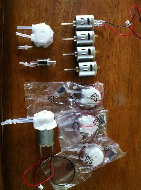
Because a picture is worth a thousand words
Do not forget is in progress.
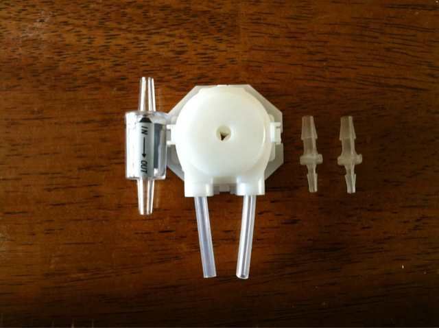
Here is the dosing pump I use
(purchased on eBay)
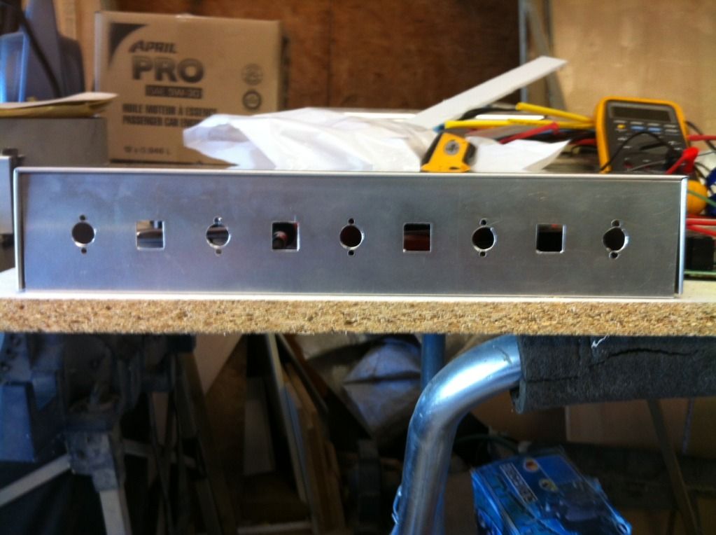
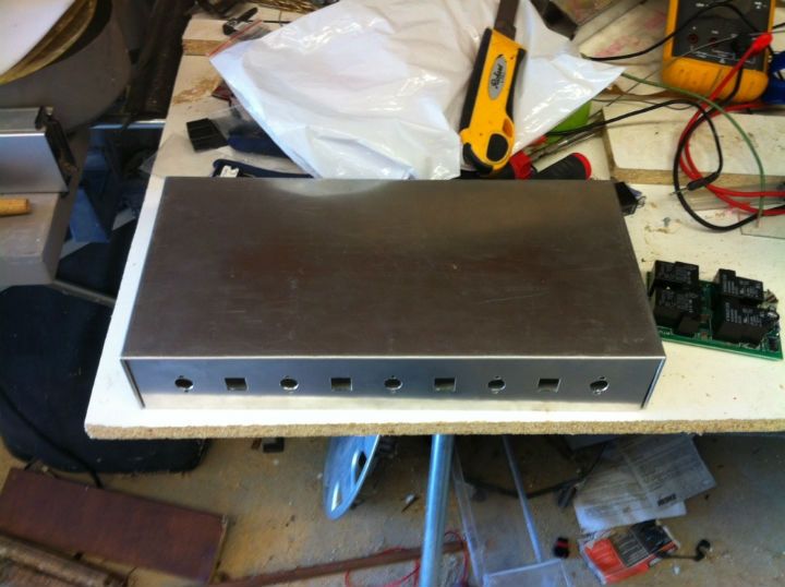
Here is my DiY case
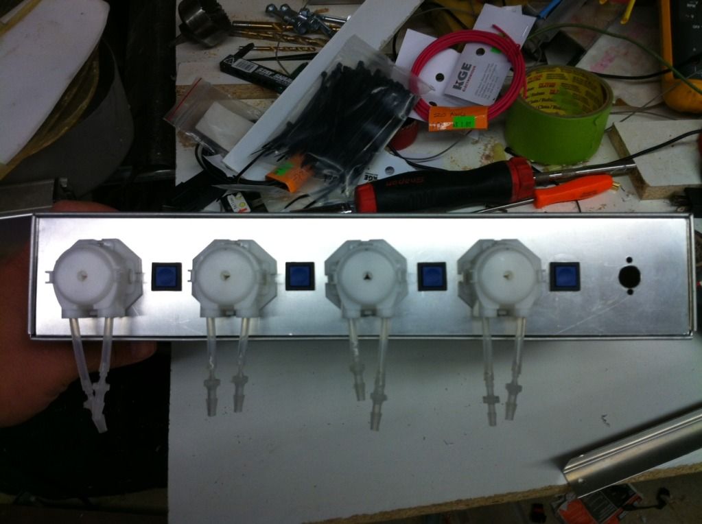
And Video
http://youtu.be/oV4HXv71SxQ
Re: Need custom code for custom expansion
Posted: Wed Oct 24, 2012 11:22 am
by rimai
no pics

Re: Need custom code for custom expansion
Posted: Wed Oct 24, 2012 12:42 pm
by DrewPalmer04
Where'd you get the bare doser motor? 12v I'm assuming?
Re: Need custom code for custom expansion
Posted: Wed Oct 24, 2012 3:16 pm
by AquaO
I corrected the link of the pics, sorry
I bought the motor on ebay, I believe that it is the same as Profilux.
Yes they are 12v
I was also working to change the speed of the motor manually, for avoided programming all the time.
Re: Need custom code for custom expansion
Posted: Wed Oct 24, 2012 3:31 pm
by DrewPalmer04
So jealous...I need an Uno now...
Good DIY!!!
Re: Need custom code for custom expansion
Posted: Thu Oct 25, 2012 8:21 am
by lnevo
AquaO,
That is awesome! I just bought a few of those pumps, actually I bought the $30 ones that are already in an encosure with a potentiometer. I would love to convert it at some point to do what you did and control them individually with PWM instead of relays on my outlet strip...
Do you think you could do a more comprehensive post on what you did to setup the UNO? Do you know what would be needed if I wanted to just integrate with the RA Dimming module?
Thanks in advance and again awesome job!
Edit: Wow, the UNO is only $35... I'd gladly purchase one of these if I knew what to do with it!