Temp Probe Expansion Module (DIY)

Expansion modules and attachments
Post Reply
tkeracer619
Posts: 159
Joined: Thu Nov 24, 2011 9:50 pm
Location: Golden, CO

Temp Probe Expansion Module (DIY)

Post by tkeracer619 »

Needing more temp probes and not wanting a bunch of Y harnesses I decided to put together my own Temp Probe Expansion Hub. I wasn't really interested in building one on a breadboard but was hoping for something a little more finished. Currently the info needed to add additional probes is scattered around so I am starting this thread in hopes of consolidating it. ReefAngel uses DS18B20 temperature probes. They are not I2C but are OneWire.

Threads of interest.
http://forum.reefangel.com/viewtopic.php?f=4&t=3415
http://forum.reefangel.com/viewtopic.ph ... 4&start=10

Code for adding more temp probes.

Code: Select all

ReefAngel.AddExtraTempProbes();
My DIY Temp Probe Expansion Hub.
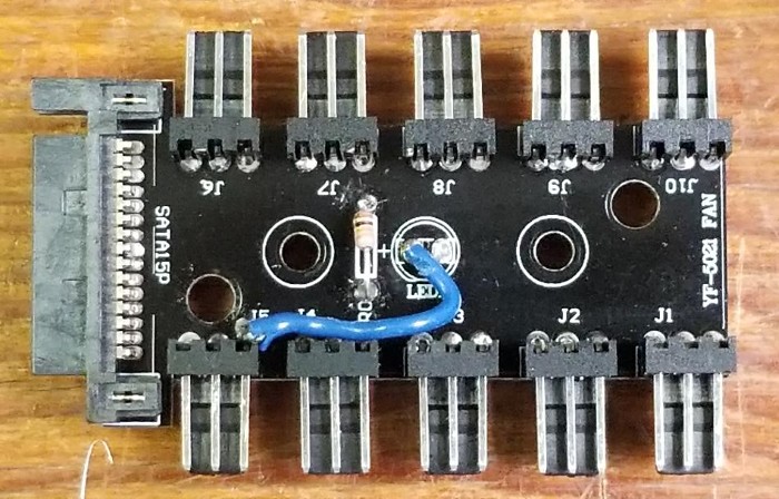
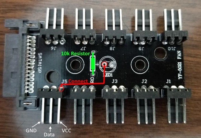
I settled on a Thermaltake AC-007-AN1NAN-A1 Commander FX SATA Powered 10 Port Fan Hub. It worked ok but if I were to do this again I would look for another hub. This one had no visible traces and only had two pins connected, the pins we will use for +Vcc were not connected so that took some additional effort. This board did have an LED which was nice as I was able to use the additional circuitry to mount the recommended 10k resistor between the Data pin and +Vcc. If anyone else does this and goes a different route please show how you did so.

Here is the Hub.
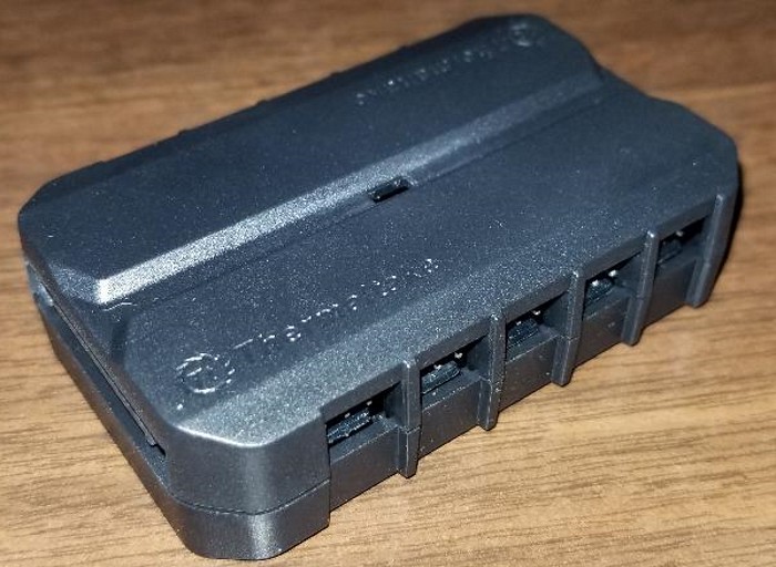
Image

This is what it looks like when you take it apart, there are two screws holding it together under the sticker on the backside.
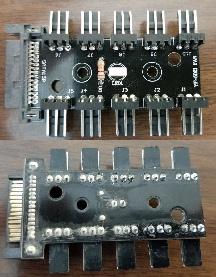
Image

First step is to remove the LED and the Resistor. Use a good soldering Iron and solder pump.
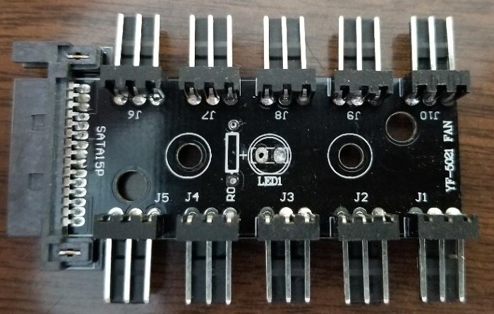
Image


2nd step is adding a 10k resistor where the original one was and connecting a 24ga wire from +LED to Pin J5.
Image
Image

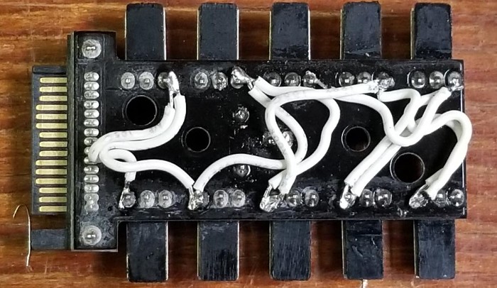
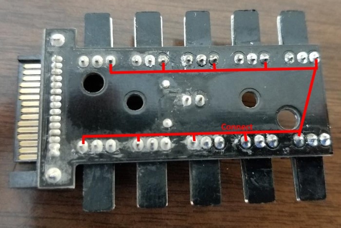
3rd step is connecting all of the +Vcc pins together on the backside. I used some 26ga wire.
Image
Image

4th step is to test that you have continuity between +Vcc pins, 10k ohm resistance between Data and +Vcc pins, and continuity between all GND pins as seen in step 2. Re-Assemble and the Expansion Module should be good to go.
Image
tngo
Posts: 139
Joined: Wed Apr 27, 2011 9:08 am

Re: Temp Probe Expansion Module (DIY)

Post by tngo »

That's a pretty nifty DIY tkeracer619. The AddExtraTempProbes function can support up to how many temperature probes?
binder
Posts: 2865
Joined: Fri Mar 18, 2011 6:20 pm
Location: Illinois
Contact:

Re: Temp Probe Expansion Module (DIY)

Post by binder »

tngo wrote:That's a pretty nifty DIY tkeracer619. The AddExtraTempProbes function can support up to how many temperature probes?
3 additional probes, giving you 6 total.


Sent from my iPad using Tapatalk
tkeracer619
Posts: 159
Joined: Thu Nov 24, 2011 9:50 pm
Location: Golden, CO

Re: Temp Probe Expansion Module (DIY)

Post by tkeracer619 »

Thanks.

I believe you can use more than 6 but that code gives you 6 on the display and portal. I need 11 minimum.
Image
Post Reply